


![]()
1.Description:
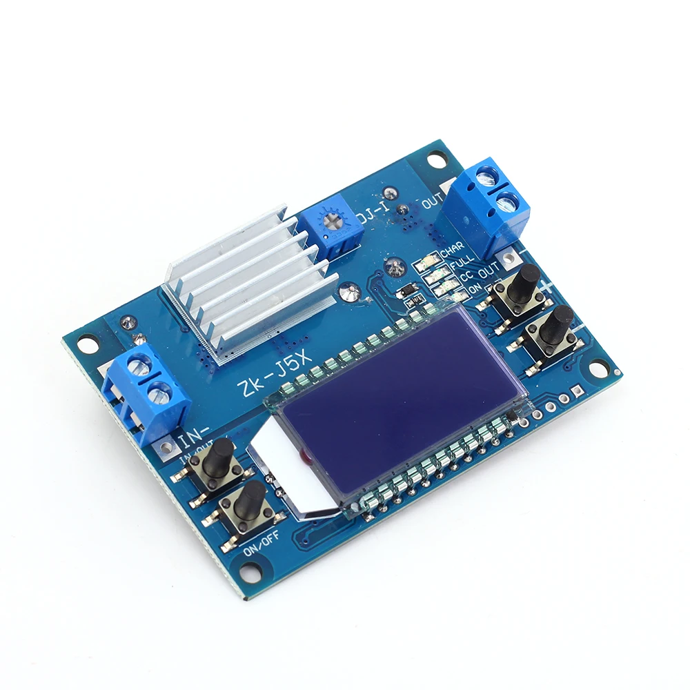
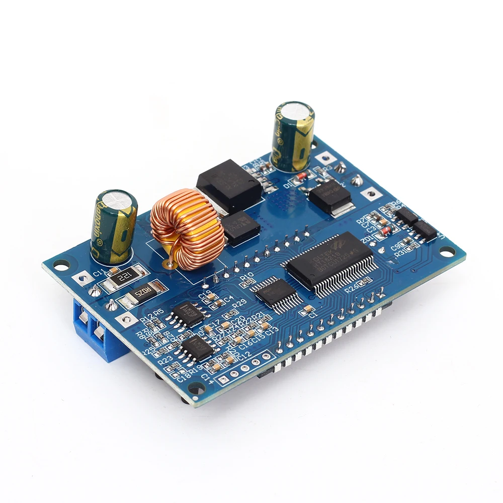
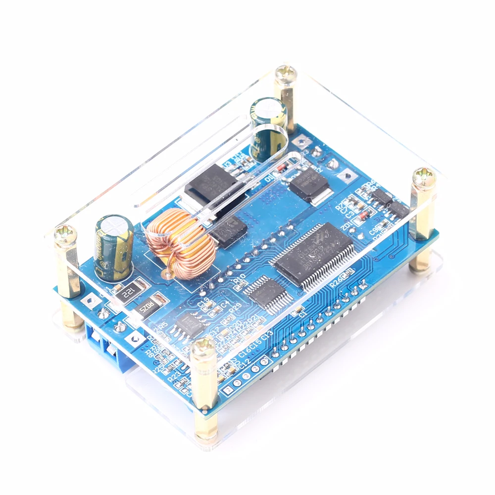
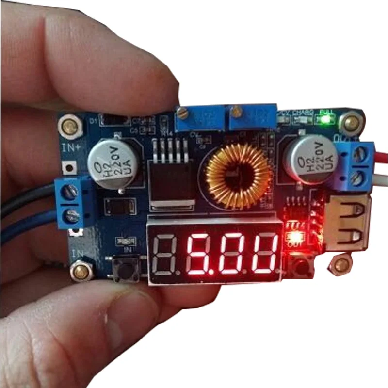
ZK-J5X is a DC adjustable constant voltage constant current step down power supply module with LCD display.HD display input voltage and output voltage, current, power and display status.Adjustable stable output voltage and current.Set output current to meet the demand.It can be used as ordinary buck power supply module, charger and LED constant current driver.Simple and efficient, practical.
2.Features:
1>.High voltage resistant terminal;
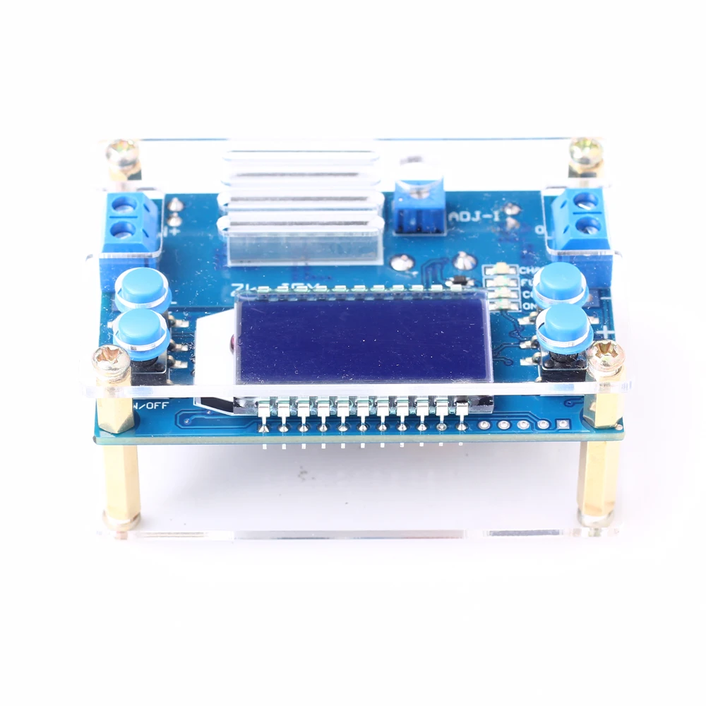
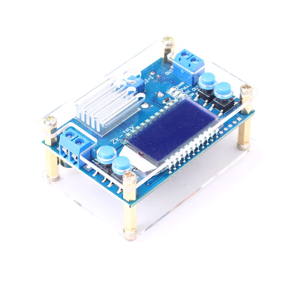
2>.With high quality acrylic shell;
3>.Support complete disability output;
4>.Support anti-reverse protection;
5>.Support short circuit protection;
6>.Support enable output;
7>.LCD screen HD display;
8>.Support charging function;
9>.Support select output;
10>.Support display input voltage;
11>.Support display output voltage, current, power;
12>.Support working status indicator;
13>.Multiple parameters are displayed simultaneous;
14>.High current, low heat;
3.Parameters:
1>.Product Name:ZK-J5X 5A Step Down Power Supply Module
2>.Product Number:ZK-J5X
3>.Working Voltage:DC 6.5V-36V
4>.Output Voltage:DC 1.2V-32V
5>.Output Current:5A(4.5A need heat sink;3.5A is stable for long time)
6>.Output Power:75W(75W need heat sink;50W is for 3.5A)
7>.Voltage Display Range:1.2~32V
8>.Voltage Display Precision:+/-0.1V
9>.Voltage Display Resolution:0.05V
10>.Current Display Range:0~5A
11>.Current Display Precision:+/-0.05A
12>.Voltage Display Resolution:0.005A
13>.Conversion efficiency:About 94%
14>.Working current:30mA
15>.Soft Starter:Yes(Failure at high power load)
16>.Anti-reverse Protection:Yes
17>.Anti-backflow Protection:No(It is recommended to connect a diode in series at the ‘OUT+’)
18>.Working Temperature range:-20℃~85℃
19>.Working Humidity range:0%-95%RH
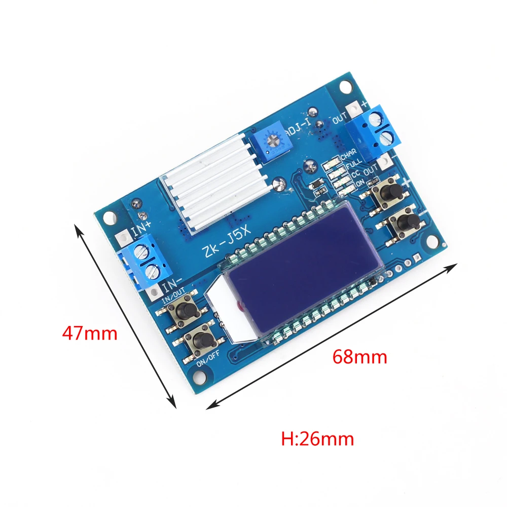
20>.Size without shell:68*47*26mm
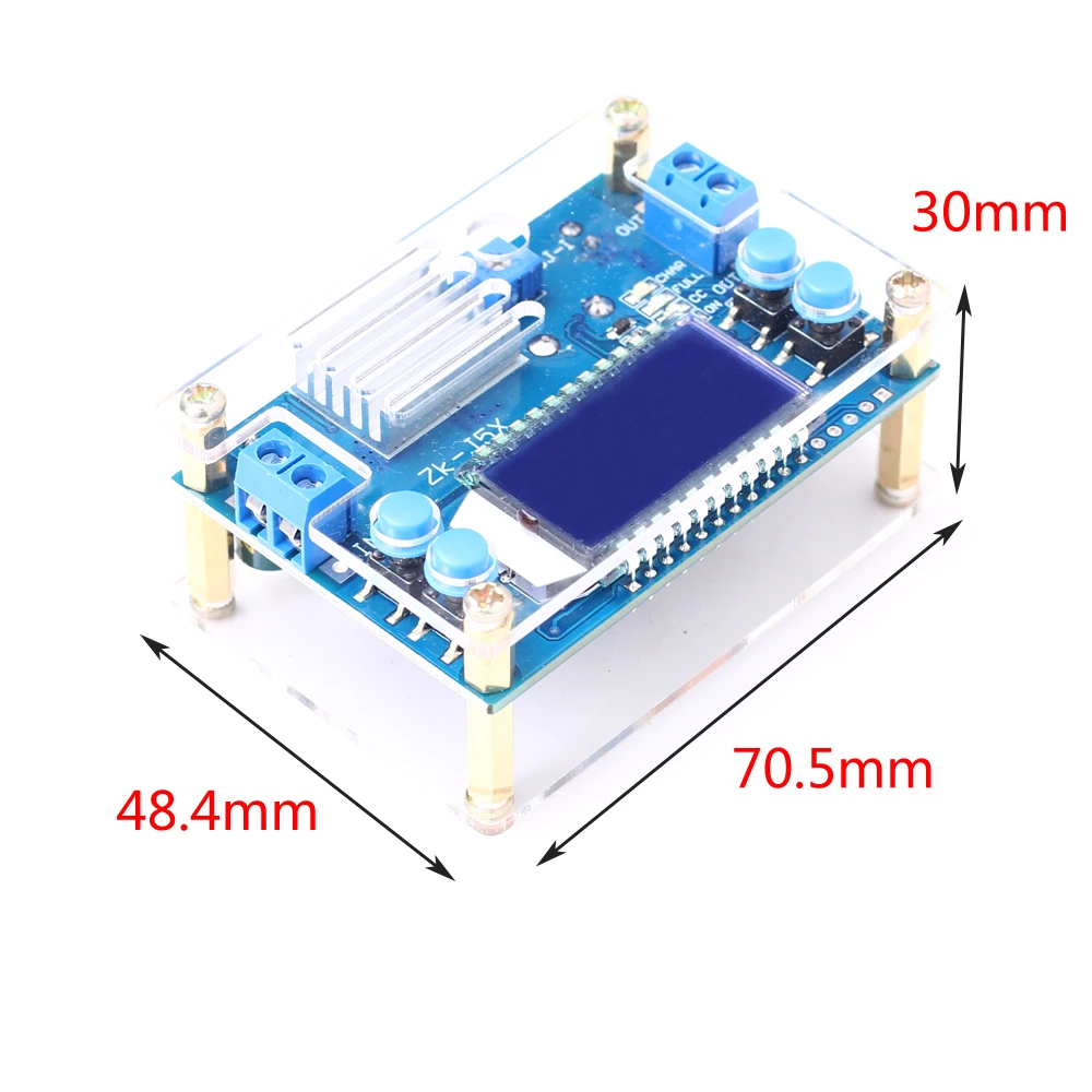
21>.Size with shell:70.5*48.4*30mm
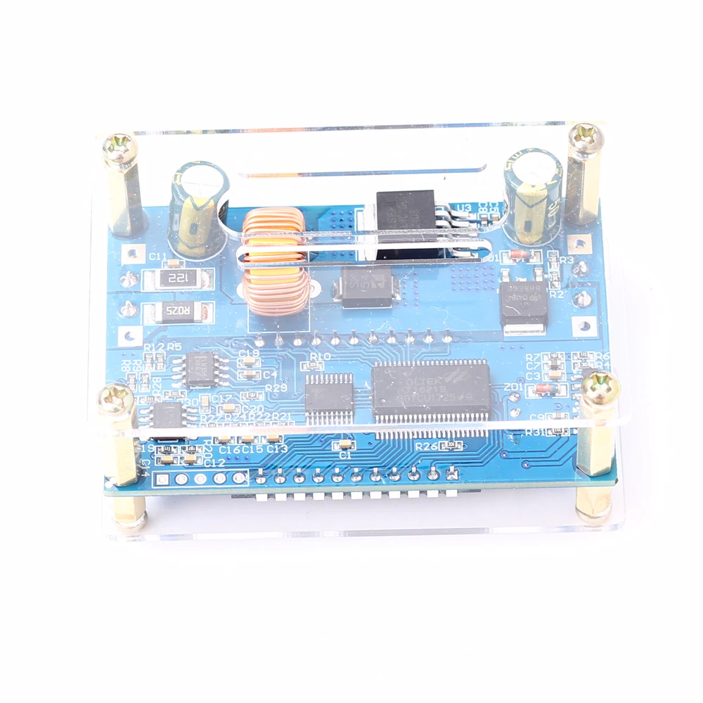
22>.Heat Sink Size:20*14*6mm
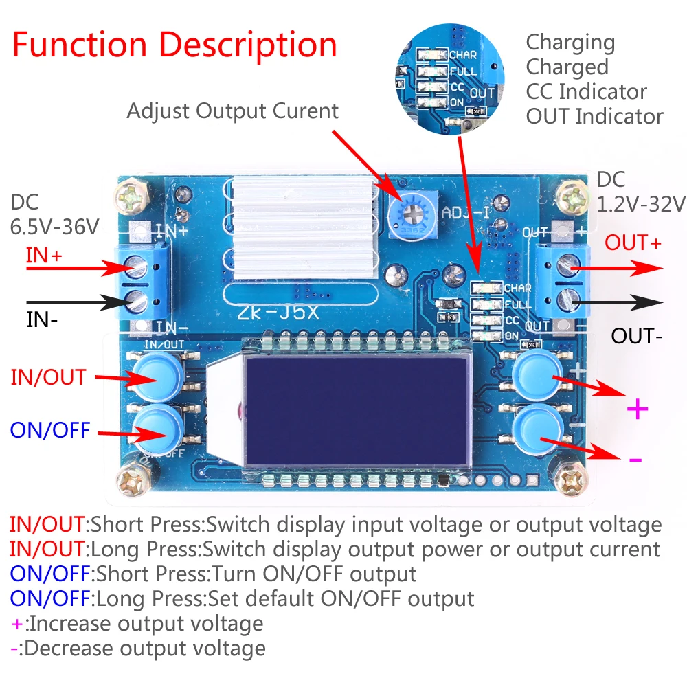
4.Button/Potentiometer/LED introduction:
1>.Long press means need keep press for more than 3second.
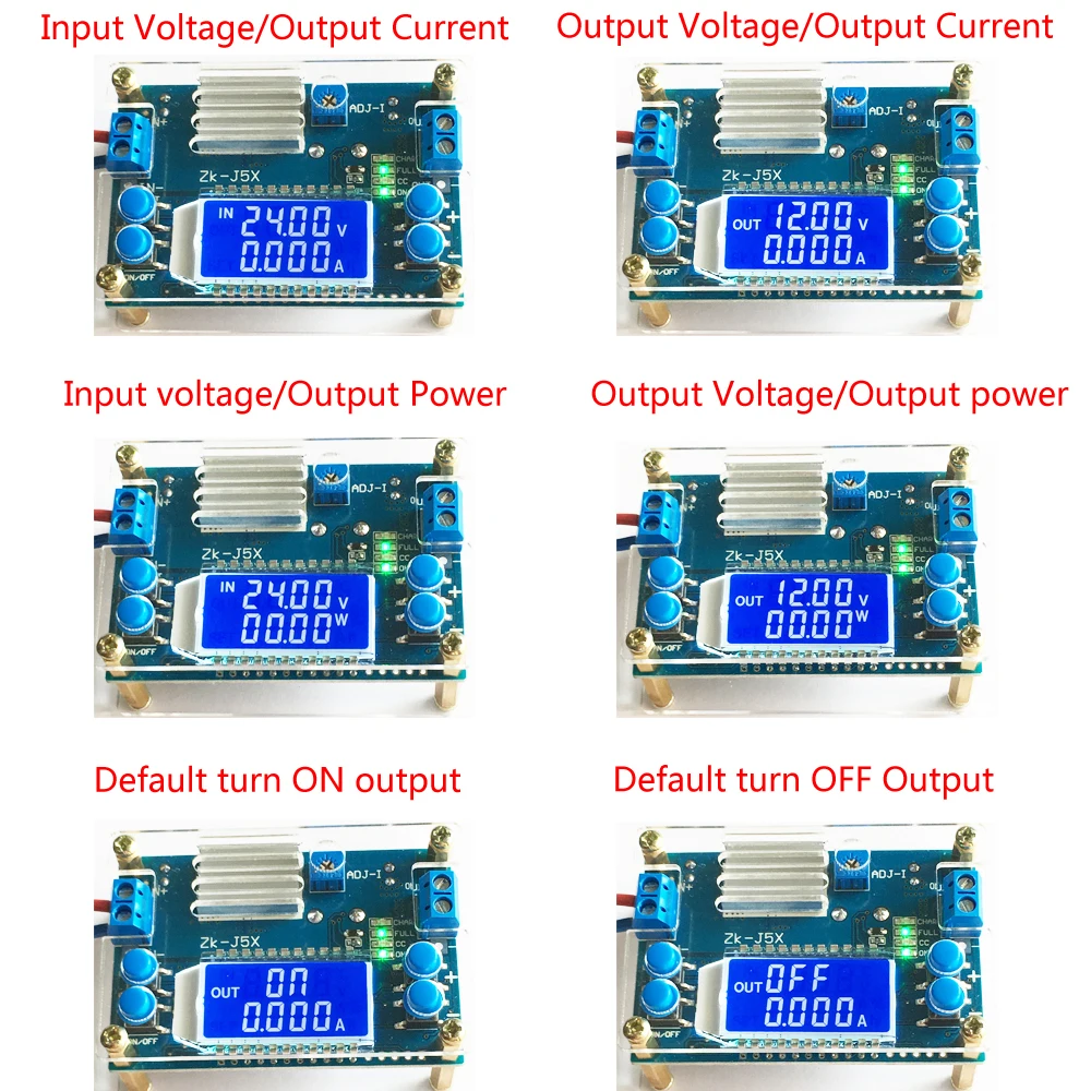
2>.ON/OFF:Short Press to select whether output voltage.Long press is used to restore default settings for next re-power.
3>.IN/OUT:Short Press to switch display input voltage or output voltage.Long press is used to switch display output current or output power.
4>.’+’ Button:It is used to regulate output voltage.Increase output voltage.Each time the button is pressed for short press,the output voltage is increased by 0.05V.Long press can continuously increase.Increase 0.1V, 1V in continuous if keep long press again.
5>.’ - ’ Button:It is used to regulate output voltage.Decrease output voltage.Each time the button is pressed for short press,the output voltage is decreased by 0.05V.Long press can continuously decrease.Decrease 0.1V, 1V in continuous if keep long press again.
6>.ADJ-I Potentiometer:Adjust output current.Increase the output current when rotating clockwise.Module enters constant current output state if load current reach the Set Current Value.Constant current Red LED indicator CC will turn ON.
7>.ON LED:Green LED.Output indicator.It will turn ON when there is a output at output terminal.Otherwise it is OFF.
8>.CC LED:Red LED.Constant current output indicator.It enters the constant current state when the load current reaches the set current and CC constant current indicator turns ON.
9>.FULL LED:Green LED.Charged fully indicator.When battery is charged fully.It will turn ON.It will turn ON if output current is less than 0.2A when the Set Current is 2A.
10>.CHAR LED:Charging indicator.It will turn ON when charging.
5.Using Steps:
1>.As a ordinary step down power module:
1.1>.Connect right input voltage at input terminal;
1.2>.Adjust ’+’ and ’ - ’ constant voltage buttons to set output voltage according to require.
1.3>.Rotate ADJ-I potentiometer counterclockwise more than 10 turns at first.
1.4>.Test Output short circuit current by multimeter at 10A or 20A(Connect two Test Probes to output terminal on module)
1.5>.Rotate ADJ-I constant current potentiometer clockwise to set output current according to require overcurrent protection value.
1.6>.Test and using(E.g:Module’s maximum output current is 2A if display 2A on multimeter.Then the maximum current can only be 2A when use this module.Red LED indicator will turn on if output reach to 2A.Otherwise LED is OFF.)
1.7>.The output voltage will decrease due to the current sampling resistor at the output. The higher the current, the more the voltage is reduced.
2>.As a charger:
2.1>.Tops:Power module can not be used as charger module if it does not support constant current function.The voltage difference between the battery with insufficient voltage and the charger is very large.That causes excessive charging current even damage the battery.So it needs keep charging in constant current mode to reaching a certain level.Then automatically switch back to constant voltage charging.
2.2>.Make sure floating charge voltage and charge current for battery.If the lithium battery’s parameter is 3.7V/2200mAh, then the float charge voltage is 4.2V, and the maximum charging current is 1C, which is 2200mA.
2.3>.Connect right input voltage at input terminal.(Note:Please don’t connect load during set parameter).
2.4>.Test output voltage by multimeter and adjust ’+’ and ’ - ’ constant voltage buttons to make sure output voltage reach to require floating charge voltage.(If charge a 3.7V lithium battery, adjust the output voltage to 4.2V)
2.5>.Rotate ADJ-I potentiometer counterclockwise more than 10 turns at first.
2.6>.Test Output short circuit current by multimeter at 10A or 20A(Connect two Test Probes to output terminal on module)
2.7>.Rotate ADJ-I constant current potentiometer clockwise to set output current according to require charge current value.
2.8>.Connect battery at output terminal and start to charging.
3>.As a high power LED constant current driver:
3.1>.Make sure LED’s working current and maximum working voltage.
3.2>.Connect right input voltage at input terminal.(Note:Please don’t connect load during set parameter).
3.3>.Test output voltage by multimeter at output terminal and adjust ’+’ and ’ - ’ buttons to set output voltage to LED’s maximum working voltage.
3.4>.Rotate ADJ-I potentiometer counterclockwise more than 10 turns.
3.5>.Test Output short circuit current by multimeter at 10A or 20A(Connect two Test Probes to output terminal on module)
3.6>.Rotate ADJ-I constant current potentiometer clockwise to set output current according to require LED working current.
3.7>.Connect LED and test.
6.Note:
1>.Default output voltage is about 5V.
2>.It is a step down power supply module,So the output voltage must be lower than input voltage.Otherwise it will not working normally.
3>.Please press button ’ - ’ repeatedly if there is no output voltage.
4>.It is a DC power module,So it can not connect to AC power.
5>.Please don’t short output.
6>.Input voltage must be 0.5V higher than output voltage.
7>.Please connect input before connect battery when use as charge and make sure output voltage is higher than battery voltage.It is recommended to serial a anti-backflow diode at input positive terminal.
8>.’IN-’ and ‘OUT-’ can not be connect together,otherwise module can not support constant current output.
9>.Please make sure input power is more than load power.
10>.Please step down output power if module is hot.
11>.The module's output voltage and current accuracy are 0.1V and 0.05A.
12>.Please read use manual and description before use.
7.Application:
1>.Ordinary power supply;
2>.Battery charger;
3>.LED drive power;
4>.Instrument voltage display;
5>.Test meter;
6>.Circuit test;
7>.Power conversion.
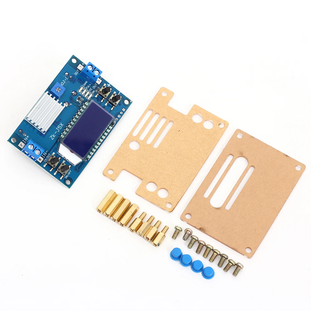
8.Package:
1>.1pc ZK-J5X 5A Step Down Power Supply Module;
2>.1pc 20*14*6mm Heat Sink;
3>.2pcs Acrylic shell;
4>.4pcs Blue button cap;
5>.4pcs M3*15mm Copper column;
6>.4pcs M3*8+6mm Copper column;
7>.8pcs M3*5mm Screw.
===================================================================================================
Model:5140
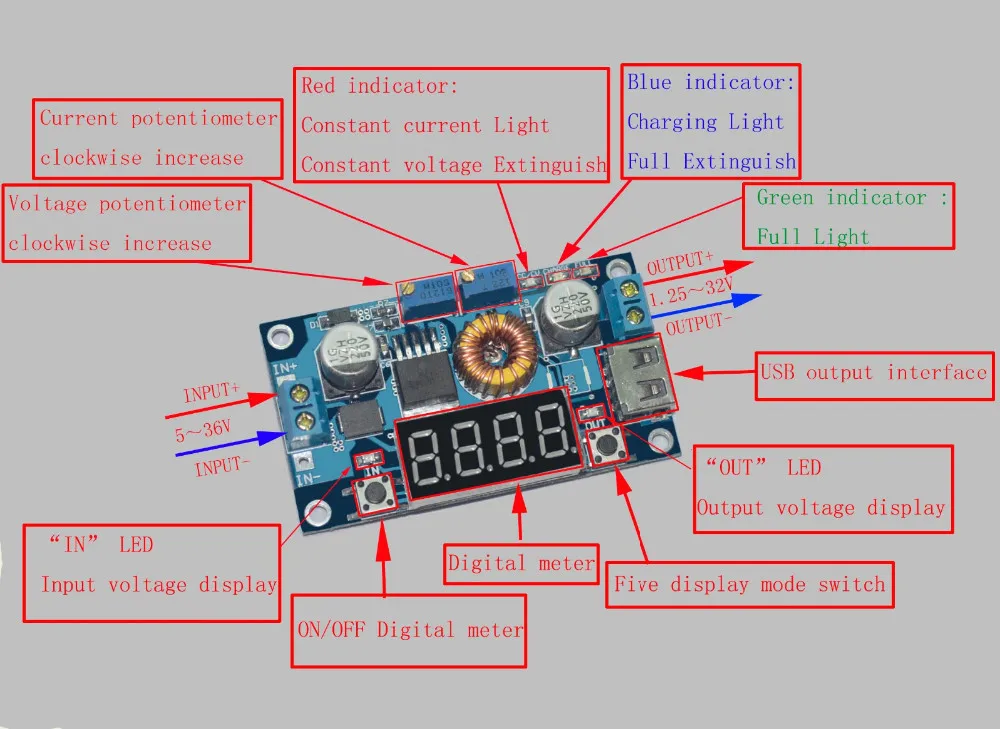
Highlights :
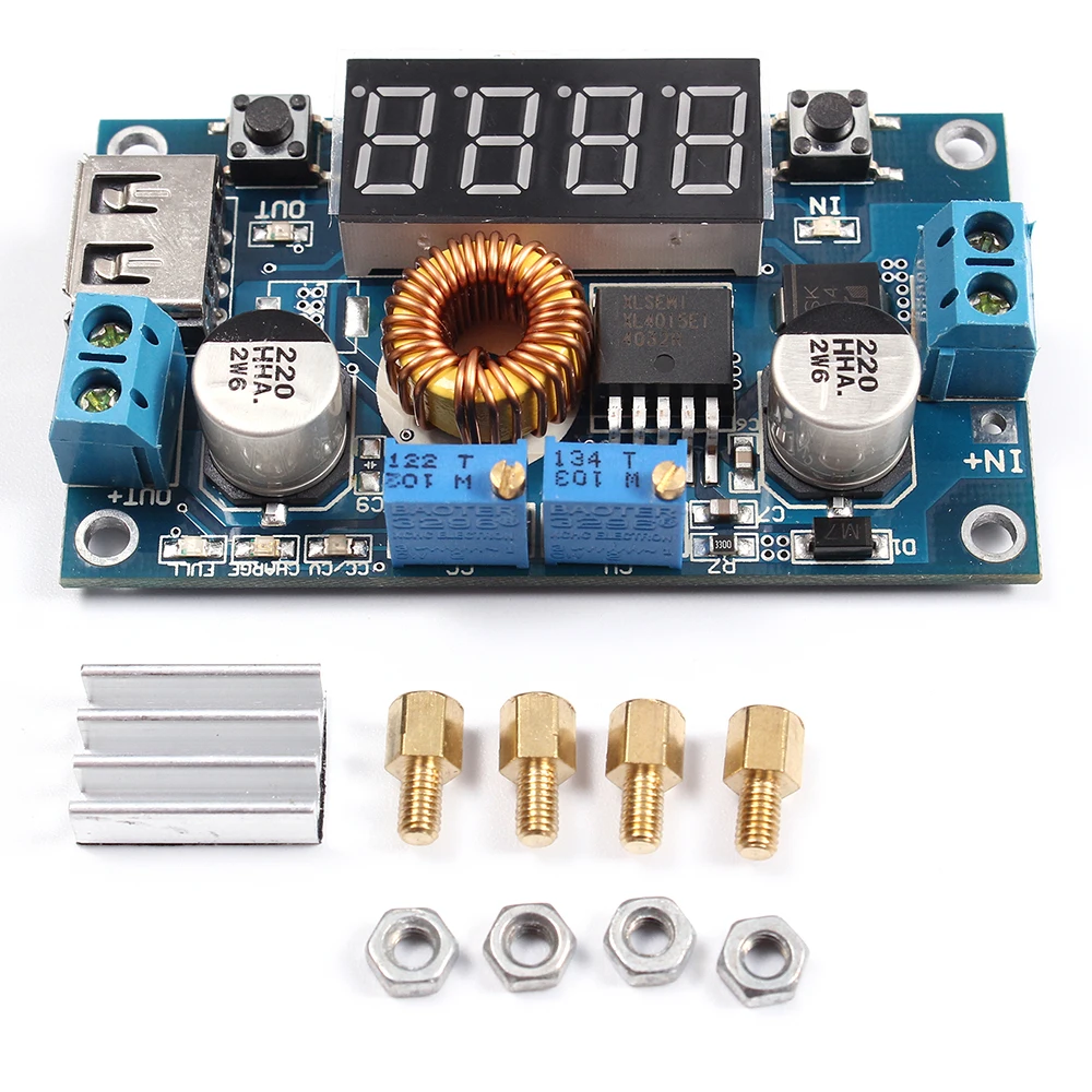
Contains the voltmeter, ammeter, power meter, USB interface for charging the digital products.
Note:
1.When you use the product, the module inputs and outputs to be isolated from ground.
2.USB output voltage is consistent with the module, not a fixed 5V output. When charging for digital equipment, make sure USB output voltage is 5V.
3.Some customers report: “The module can not adjust the output voltage is always equal to the input voltage.” When you encounter this problem, please counterclockwise rotation of the “voltage potentiometer” 10 laps or more, then use the module you can adjust the output voltage. Because the factory default output voltage of about 20V.
Specifications
1.Input voltage range:5-36VDC
2.Output voltage range:1.25-32VDC adjustable
3.Output current: 0-5A
4.Output power: 75W
5.High efficiency up to 96%
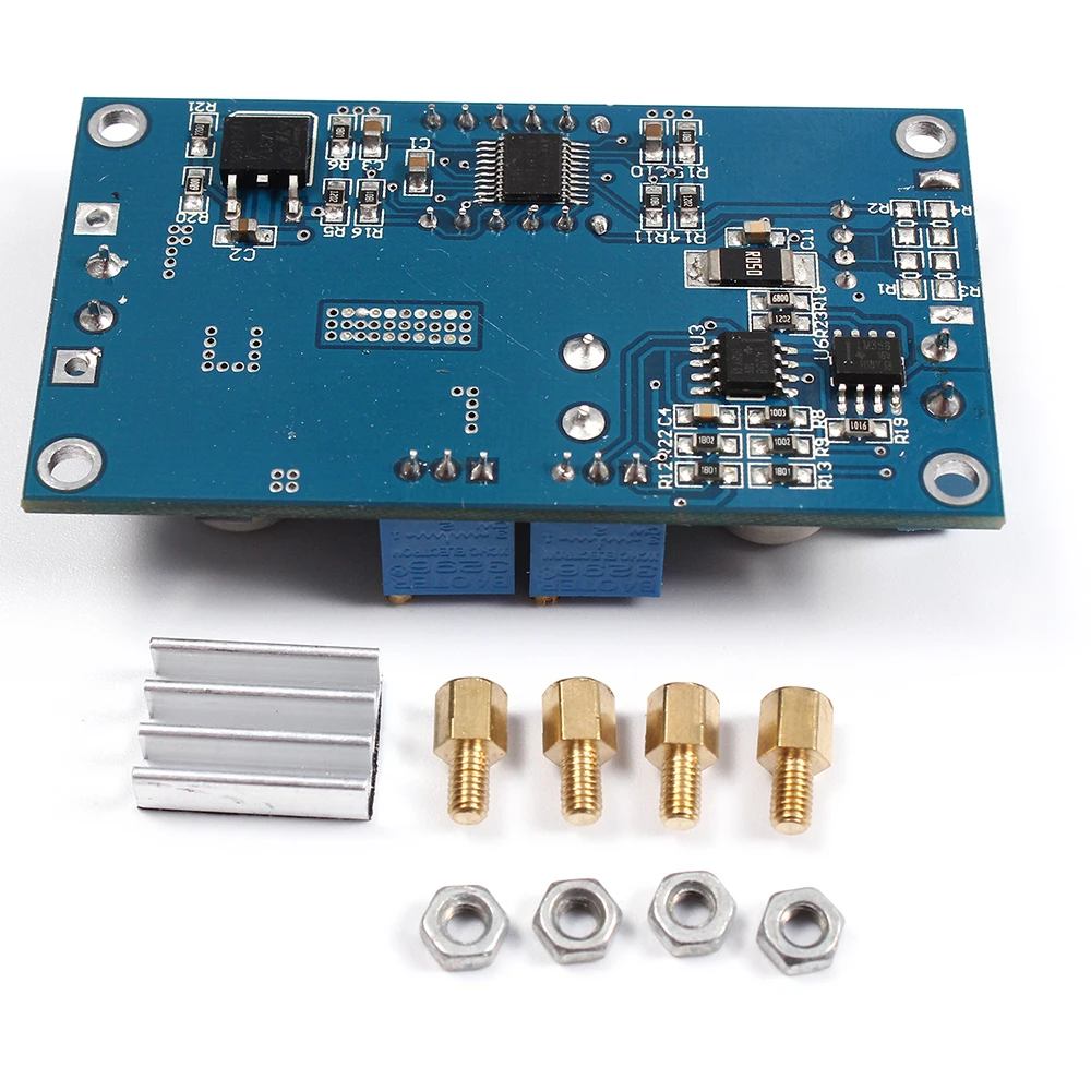
6.Built in thermal shutdown function
7.Built in current limit function
8.Built in output short protection function
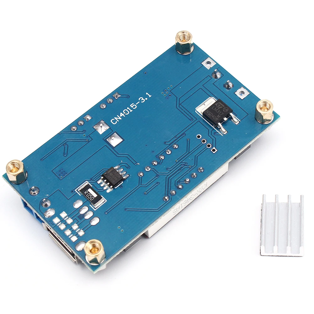
9.Input reverse polarity protection: None (if required, high current diode in series with the input).
10.L x W x H =68.2×38.8×15mm
Application
1.Use as a step-down modules with overcurrent protection
Usage:
(1) Adjust the right button so that “OUT” LED lighted, Digital meter shows the value of output voltage ,adjust the “voltage potentiometer” so that the output voltage reaches the value you want.
(2) Adjust the right button so that Digital meter shows the value of output current;Wire shorted output terminal, then adjust the “current potentiometer” so that the output current reaches a predetermined overcurrent protection value. (For example, the Digital meter displays the current value of 4A, then you can use the module to a maximum current of 4A)
(3) Connected to the load.
2.Use as a battery charger
Usage:
(1) Make sure you need to charge the battery float voltage and charging current; (if lithium parameters 3.7V/2200mAh, then the float voltage is 4.2V, the maximum charging current 1C, ie 2200mA)
(2)Under no-load conditions, adjust the “Voltage potentiometer” so that the output voltage reaches the float voltage; (if to 3.7V rechargeable lithium battery, the output voltage can be adjusted to 4.2V)
(3)Adjust the right button so that Digital meter shows the value of output current;Wire shorted output terminal, then adjust the “current potentiometer” so that the output current reaches a predetermined Charging current value.
(4)Charge turn lamp current factory default is 0.1 times the charging current; (Battery during charging current is gradually reduced, if the charge current setting is 1A, then when the charge current is less than 0.1A, blue lights turned off, the green light is on, which means that the battery is fully charged)
(5)connected to the battery charge.
(1,2,3,4 steps as: Output is unloaded, do not connect the battery)
3.Use as a LED constant current driver module
Usage:
(1)Adjust the “voltage potentiometer” so that the output voltage reaches the value you want.
(2)Adjust the right button so that Digital meter shows the value of output current;Wire shorted output terminal, then adjust the “current potentiometer” so that the output current reaches a predetermined LED operating current.
(3)Connect LED, work.
(1,2 steps as: Output is unloaded, do not connect LED)
Voltmeter and ammeter calibration method:
Module with manual calibration function can correct display precision voltage and current, if you think the current voltage and current accuracy to meet the requirements, do not perform the following operations.
(1) Output voltage calibration steps
Step 1, adjust the right button so that “OUT” LED lighted, Digital meter shows the value of output voltage; Press the right button for more than 2 seconds, release, Digital meter and “OUT” LED flashes in synchronization so that you enter the output voltage calibration mode.
Step 2, press the right button (normal speed), the voltage value is adding up a unit; Press the left button, minus a unit; Due to a unit is less than 0.1V, the minimum voltage display to 0.1V, so you need to continuously press 1-5 times to see the voltmeter change 0.1V, how many times voltmeter change 0.1V by pressing the key, depending on the current display voltage, the higher the voltage, the fewer the number of press.
Step 3, press the right button for more than 2 seconds, release, to exit the output voltage calibration mode. All parameters set to automatically power down to save.
(2) Input voltage calibration steps
Step 1, adjust the right button so that “IN” LED lighted, Digital meter shows the value of input voltage; press the right button for more than 2 seconds, release, Digital meter and “IN” LED flashes in synchronization so that you enter the input voltage calibration mode.
Steps 2 and 3, consistent with the output voltage calibration method.
(3)Output current calibration steps
Step 1, adjust the right button so that Digital meter shows the value of output Current. Press the right button for more than 2 seconds, release, Digital meter flashes in synchronization so that you enter the output current calibration mode.
Step 2,Connected to the load, ammeter in series, adjust the right and left button to change the display of digital meter, so that is consistent with the ammeter display .
![]()
Experience the convenience of swift order fulfillment with our top-notch Shipping services.


-
 FAST SHIPPING
Speedy shipping ensures your order arrives as soon as possible
-
 Secure Payment
Shop with confidence using safe, encrypted checkout.
-
 Return Policy
Get a refund or exchange within 30 days, no stress.
-
 Happy Customers
Thousands of happy customers trust and adore our products.

Speedy shipping ensures your order arrives as soon as possible

Shop with confidence using safe, encrypted checkout.

Get a refund or exchange within 30 days, no stress.
Thousands of happy customers trust and adore our products.